This unit was originally designed to convert a Yaesu FT790 to transmit fast scan (live) television pictures. Most small FM transceivers can be modified to do the same with this design.
I think this was first published in the RSGB's Amateur Radio Handbook. They asked to print it but never sent me a proof copy to see for myself!
This simple design allows ATV to be transmitted from a low-power (up to about 3W) FM or CW transmitter. Ideally the transmitter should use CW mode and have its 'key' down but an FM rig will work just as well if the microphone is disconnected and the PTT switch is closed. The only reason for disconnecting the microphone is to prevent sounds from it frequency modulating the carrier.
All the design does is interrupt the supply current to the power amplifier and possibly also the driver stage of the transmitter. It allows the depth of modulation to be set and the quiescent PA current. Setting the current is important because almost all small transmitters run their output stages flat out but for AM, the power needs to both decrease and increase above mean level.
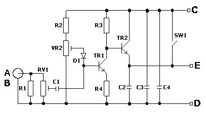
As the unit only requires three connections to the transmitter, it can be mounted outside the rig if preferred. Connections A and B are the video input and should be fed through a screened 75R impedance cable. Connection C goes to the existing PA supply line and connection E goes to the PA stage(s). If SW1 is closed the rig essentially returns to its previous functionality. Connection D is the 0V ground to the negative side of the rig's supply.
Setting up is quite easy:
With the switch closed, make sure the rig behaves normally. Open the switch and check that adjusting RV2 makes the rig's output power vary. It should go from near normal down to almost nothing.
Apply a standard 1 Volt p-p video signal across A and B, a camera can be used if one is to hand. Start with RV1 set to mid-position and while monitoring on a TV receiver, adjust RV2 until a locked picture can be seen. Adjusting too far one way will cause the sync pulses to compress and the picture will tear or roll, going too far the other way will cause white areas to smear, looking rather like an over-exposed photograph. Set it half way between these points.
Now adjust RV1 for optimum contrast, you will find the controls interact slightly so it might be necessary to adjust RV2 again to clean the picture up. When set correctly a solid, fully contrasted picture should be seen.
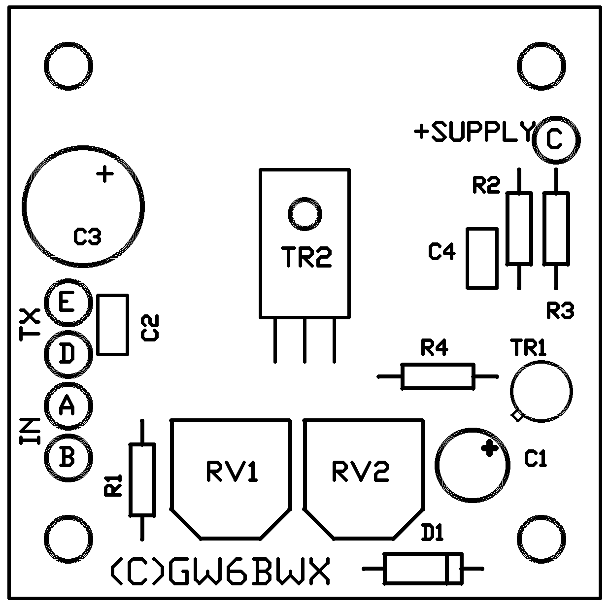
Parts List:
| R1 |
270R |
| R2 |
1K5 |
| R3 |
820R |
| R4 |
82R |
| C1 |
10uF |
| C2 |
47pF |
| C3 |
220uF |
| C4 |
100nF |
| TR1 |
2N2222 |
| TR2 |
BD131 |
| VR1 |
100R |
| VR2 |
470R |
| D1 |
1N4148 |
| SW1 |
see text |
SW1 can be any single-pole switch capable of carrying the PA stage current, normally this is less than 1 Amp. TR2 will require a small heat sink, the PCB has room to fit one.
Note: If possible cut the existing PA supply feed AFTER any large (>470pF) decoupling or filter capacitors so they they are connected on the "C" side of the schematic rather than the "E" side.
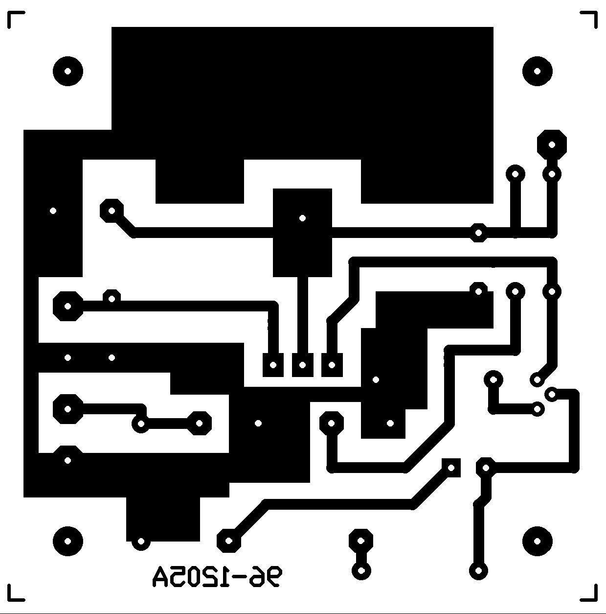
Click HERE to go to downloadable PCB files.