Testing:
Before applying power, check for shorts on the board. This design runs from a FIVE volt supply, connecting it directly to a 12 volt supply will kill it for certain. The current drawn is very small, in the region of 70mA so connect a small 5V regulator in line with the supply if you intend to use a 12V power source. For the prototypes I used a standard 7805 regulator on a 2cm square copper sheet and even after running for two days it was barely warm to touch. When you are happy that the current consumption is OK, measure the voltage between ground and each of the outputs, it should be less than 0.5V. If all is well you can connect a monitor to the video and audio outputs then put the unit in "self-test" mode by pressing the "Chan A both" and "DTMF" function keys simultaneously. You should hear alternating high and low pitched beeps at about 1 second intervals. Next, connect some audio and video sources to the inputs, in self-test mode the inputs are selected in sequence so you should see and hear the sources being selected one after another. Channel A and B sequences are staggered so you can confirm their independent operation. To exit "self-test" mode you can either switch the power off and on again or press and hold the "Chan B both" and "Antenna select" keys together until a rapid beeping is heard. You can release the keys as soon as the beeps start and after a few seconds the unit will initialise itself to its newly powered up state.
An 8-input 2-channel Audio and Video Switch with Keypad control.
This article first appeared in 'P5' magazine - September 1995
The design described here is for a compact, low-cost signal router that can feed any of eight audio inputs and eight video inputs to two pairs of outputs. It also includes a DTMF tone generator and an automatic antenna selector circuit. All the functions are controlled from a pair of keypads, the function keypad decides on which mode is to be used while the numeric keypad allows digit or channel selection. Antenna selection is achieved by pressing the "AS" function key or by grounding a pin on the PCB. By connecting this pin to your transmitter it is possible to automatically select your preferred antenna every time you start a transmission. The desired antenna number is programmed by fitting links or a small switch to the smallest of the PCBs.
Instructions for use:
The power-up condition is for the keypad to be in DTMF mode with channel 1 video and sound being fed to both A and B channel outputs. The "both" function selects the audio and video channel together. For example pressing "Chan B both" followed by the 5 key will send audio input 5 to channel B audio output and video input 5 to channel B video output. The "video" keys only change the selected video output, leaving the sound selection as it was. Using the example above, pressing "Chan B video" then 2 would select video input 2 while still passing the sound from audio input 5.
Audio selection is made in the same way by pressing the Chan A or B key then a digit, in this case the video selection remains unchanged.
Construction:
All five boards can be cut from one standard Eurocard (160x100mm) PCB. The two 95-003D boards are mounted upright from the main board, this method minimises the video and audio track lengths so reducing the cross-talk between them. The function key PCB is the same height as the numeric keypad to make front panel mounting easy. The small board houses the antenna enable and selection links, as these will not require frequent adjustment, it can be mounted on the rear panel. Fit all the resistors first, then the capacitors and diodes. Keep all the wire clippings, they can be used to mount the upright PCBs later on. Note that all the upright diodes are mounted with the cathode (banded) end topmost. Next, fit the links, remaining components and finally the ICs. The PIC16C54 must be programmed before soldering it in place, an unprogrammed device will not work. The binary object file will be available on BATC web site. Contact me if you need devices programming and can't do it yourself. When mounting the upright boards their bottom edge should sit flat on the main PCB with the components facing its nearest edge. Fold the wire links flush against the boards, this will give greater mechanical stability. The mounting holes are all 3mm diameter, component holes can be 0.8 or 0.5mm diameter and the Veropin holes are 1mm diameter. Keep the keypad interconnecting wires as short as possible, they carry pulse waveforms which will easily pick up on the signal wires if they come too close to each other. The audio and video input wires should be either screened or tightly twisted with their ground wires, again this is to minimise cross-talk between inputs.
The smallest PCB is laid out so that either a DIL switch or pins and jumper links can be mounted. Three of the links are used to select the antenna number in the automatic select mode, the fourth is used to enable antenna selection automatically when the PTT is operated. Note that the "AS" function key works whether link4 is fitted or not.
| Antenna |
Fit Link S1 |
Fit Link S2 |
Fit Link S3 |
| 0 |
No |
No |
No |
| 1 |
Yes |
No |
No |
| 2 |
No |
Yes |
No |
| 3 |
Yes |
Yes |
No |
| 4 |
No |
No |
Yes |
| 5 |
Yes |
No |
Yes |
How it works:
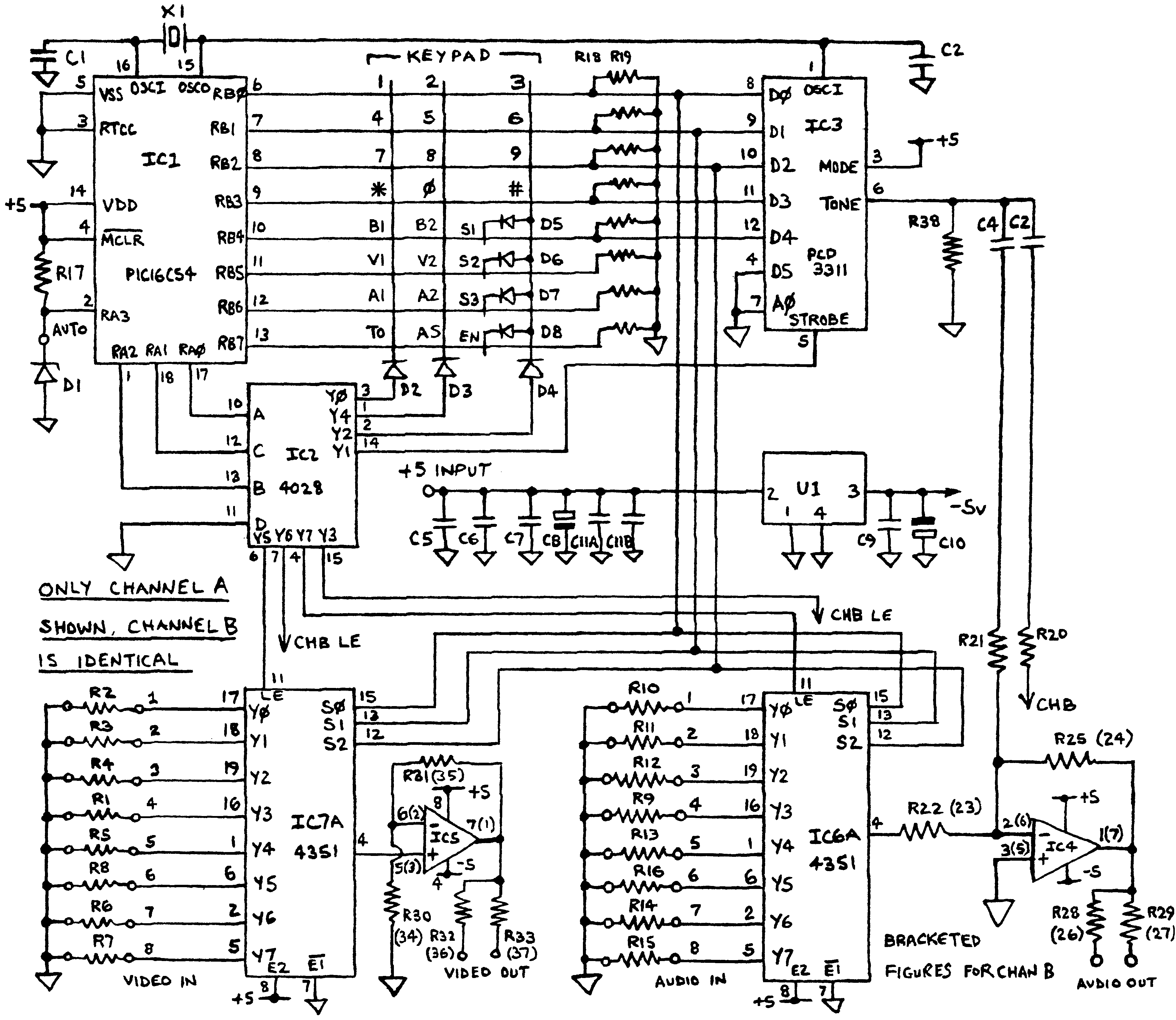
Microcontroller IC1 has a 4 bit port (RA) and an 8 bit port(RB). RA pins 0,1 & 2 carry a binary number which is decoded by IC2 to select the columns of the keypad or the select pins on the tone generator or the input selector switches. This number counts so that all the keypad columns are activated in turn. If a key is pressed while a column signal is active it connects the column signal to the RB pins where the program works out which key it was. If it was a function key the controller memorises the new mode it is to work in and applies it when the next digit key is pressed. If it was the tone mode key the digit is passed to IC3 which is a programmable tone generator, if a channel key it passes the digit to the appropriate IC6 or IC7 input selector. If RA3 pin is pulled to 0V it starts a timer which waits three-quarters of a second then sends the antenna selection signal, pressing the AS key does the same but without the delay. IC4 is the audio output buffer, it provides sufficient output power to drive two loads on each channel at once and produces a virtual earth summing point where the audio input and tones can be summed together safely. IC5 buffers the two video channels so each can drive two 75 ohm loads simultaneously. To allow DC coupling through all the channels a split supply is needed, this is provided by U1 which derives a negative five volt supply from the incoming positive five volt line. The reference frequency for the tone generator is also used as the microcontroller clock signal and is produced by IC1s internal oscillator circuit , X1, C1 and C2.
Parts List:
Parts labelled 'Farnell' are available from Farnell Electronics, other parts are from Maplin Electronics.
You can use front panel mounted switches instead of SW1-8 if preferred, in which case you will not need the FF87U switches and the alternative types can be wire linked together.
For selecting your antenna number you need either a DIL switch (Farnell 285-950) or pins and links (Farnell pins 312-241, links 312-307). If you expect to change selection often you could wire the PCB to front panel toggle switches. IC1 must be the "XT" version of the chip, and must be programmed before fitting to the board. You will also need about 1 metre of tinned copper wire to make the links on the PCBs and about 1 metre of insulated wire to connect the keypads to the main board.
Click HERE to go to the firmware and PCB files page
Use the 16C54 firmware unless you need to produce 'column 4' DTMF tones from the keypad. Hold the 'TO' key down while pressing 1, 4, 7 or * to produce A, B, C or D respectively. It is necessary to release both keys before another digit can be keyed. The '84 version also initialises so channel 1 routes to output A and channel 2 routes to channel B.
| Schematic Reference |
Quantity |
Type/Value |
Order Code |
| R1-8, 32, 33, 36, 37 |
12 |
75R |
M75R |
| R9-16, R20-35 |
22 |
1K |
M1K |
| R17 |
1 |
10K |
M10K |
| R18, 19 |
2 |
10K x 4 SIL |
Farnell 219-186 |
| R38 |
1 |
4K7 |
M4K7 |
| C1, 2 |
2 |
39pF |
WX51F |
| C3-7, 9, 11a, 11b |
8 |
100nF |
RA49D |
| C8, 10 |
2 |
10uF |
WW68Y |
| D1 |
1 |
BZY88C4V7 |
QH06G |
| D2-8 |
7 |
1N914 |
QL71N |
| X1 |
1 |
3.579MHz |
DJ31J |
| U1 |
1 |
NME0505S |
AH18U |
| IC1 |
1 |
16C54XT |
Farnell PIC16C54XTP |
| IC2 |
1 |
CD4028B |
Farnell CD4028BCN |
| IC3 |
1 |
PCD3311C |
Farnell PCD3311CP |
| IC4 |
1 |
TL072 |
RA68Y |
| IC5 |
1 |
EL2232 |
UR10L |
| IC6a, 6b, 7a, 7b |
4 |
74HCT4351 |
Farnell 74HCT4351 |
| Telephone Keypad |
1 |
4 row x 3 column |
JM09K |
| SW1-8 |
8 |
Click effect switch |
FF87U |