A PCB etching tank agitator
(aka - 'Rocking the board')
This article first appeared in CQ-TV magazine, issue 228.
This is not a full construction project but a demonstration of how parts from scrapped equipment can be put to use again to make a very useful tool. I am providing a schematic diagram and I have made the software for the microcontroller available, but the dimensions and mechanical construction depend upon salvaged parts. Being different from one construction to the next, these are left to the builders discretion.
Regular readers will know that I published an article some time ago in CQ-TV issue 200 on making printed circuit boards (PCBs) at home. The article showed my tank for developing and etching circuit boards which consisted of a plastic chocolate box (sans chocolates!) and a motor from a scrapped VCR. The motor turned a paddle which kept the chemicals in the box in motion. If the chemicals are not agitated they tend to concentrate and saturate unevenly and the board may be over processed in some places while others still need longer to become ready. The spinning paddle works very well but it does have two drawbacks, it isn't as effective in the corners of the tank as in the middle and unless switched off before being lifted from the tank it would spin rapidly when the resistance of the liquid was lost and it could flick dangerous chemicals around.
The most common method of ensuring the board gets equal treatment is to use a bubble tank. These are relatively cheap and rely on the board being suspended vertically in the chemical while air bubbles rise around it. The bubbles are produced from an aquarium air pump and leak from a perforated pipe at the bottom of the tank. As the bubbles rise they stir the liquid, keeping it on the move. The drawback to this kind of tank is that it tends to be large and it uses lots of chemical to keep the board submerged. In some circumstances this isn't a problem but personally, I like to keep dangerous chemicals safely stored in sealed bottles and have as little as possible in use at any time.
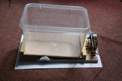
An alternative to moving the chemicals over a fixed board is to move the board, chemicals and container simultaneously, in other words rocking it from side to side. Doing this manually for long periods is very tedious but very economical on chemicals. Boards can lie flat on the bottom of the tank and only sufficient chemical to cover the board is needed. The latter approach was adopted in this design.
My first attempt at a rocking mechanism consisted of a base board made of MDF with two parallel brass rods pressed in to it. The rods pointed upward and protruded from the MDF by about 50mm. Mounted between the rods was a small 12V motor with its shaft facing upward. I fixed a threaded brass screw to the motor shaft so that it ran parallel and central between the rods. I then made another brass part, a 'platform' with three holes in it. The outer two holes were slightly larger diameter than the brass rods and the middle hole was threaded to match the screw. The intention was to use the rods as guide rails while the rotating screw drove the platform up and down, depending on the direction the motor ran. The theory was good and the prototype did work 'sort of'. What let it down was my inability to make it accurately enough, in my defence I did make it in the garden shed with hand tools, built in a proper workshop it may have worked much better. The problems was getting the rods exactly parallel and drilling the platform holes exactly on parallel axis. Although it worked, the mechanism wobbled as the screw turned and it would sometimes momentarily jam. The motor polarity was reversed by a timer and after a while it would either lock down to the base or rise so high it fell off the screw thread. If it had worked, the next stage was to fit a hook to the platform so it could lift and lower the edge of the tank and achieve the rocking motion I was after.
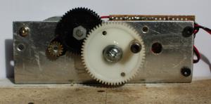
Back to the drawing board. For my second attempt I decided to accept I can't drill holes very well and a design needing less precision was conceived. Everyone who knows me will tell you I never throw anything that might be useful away. If something breaks down and cannot or need not be repaired, I always salvage useful parts before sending the remainder off to the local recycling site. To the rescue this time was a bag of two plastic gear wheels and a stepper motor which used to be the mechanism for driving the sensor back and forth in a document scanner. If I remember correctly, the scanner was quite old and was not supported by their computer operating system so its owner bought a new one and gave me the old one 'for spares'. The gears nicely meshed with each other to give a 9:1 speed reduction and stepper motors have the wonderful property of producing lots of torque at whatever speed they are driven at. They also work equally well running clockwise and anti-clockwise, unlike conventional motors which tend to wear quickly when run backwards because their brushes are 'pushed' rather than 'dragged' by the commutator.
The problem now is how to turn the rotary motion of the gears into a reciprocating motion to rock the tank. A con rod and crank mechanism, similar to that used in a car engine could be used but would be difficult to make. I didn't want to expose my poor garden shed to any more bad language so I decided to keep it simple and use the rising and falling action of a peg on the final gear as the lifting device. Keeping it simple is usually the best solution!
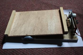
In order to tip the tank it has to be pivoted and the mechanism has to lift the end of the tank on one side of the pivot and then lower it again. Rather than make a lowering mechanism, I decided that I would let gravity do the job for me. Gravity is free and I like free things. So, instead of placing the pivot under the centre of the tank, I offset it to the side away from the lifting mechanism. This meant that most weight would be on the side with the lifter and it would natuarally fall as the lifter returned to its lowest position. If it had pivoted in the centre, it would have tipped over with no way of returning it.
This is very easy, all I did was engage the gear teeth together then using a drill as the wheel axle, twisted it against the aluminium to mark the hole position. Drilling through the marks gave the exact position the axles had to be placed. The axles themselves are made from screws, sufficient thread was left to fit nuts to secure the bracket but the section inside the wheels was gently sanded to dull the thread and prevent it cutting into the plastic. The final gear wheel has the lifting peg attached to it. The peg is a 3mm socket screw fitted with a brass sleeve (a PCB spacer). The gear wheel is drilled to 2mm close to its edge, tapped to 3mm and has the screw fitted into it with about 1.5mm passing right through the wheel. It is then secured by tightening a nut against the wheel. If you follow my example, be careful not to overtighten the nut as it will pull the screw and strip the thread from the plastic. To get the teeth to engage cleanly, thin washers were fitted to the shafts to control their distance from the axle nuts.
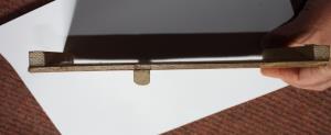
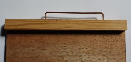
The 'slider' by which the platform is lifted is nothing more than a length of copper wire, the thick earth wire removed from an old 2.5mm T&E mains cable. It is bent into a wide 'U' shape with the ends pushed into the end of the platform. The middle (the base of the 'U') sits on the brass sleeve which lifts the slider as the peg rotates on the wheel.
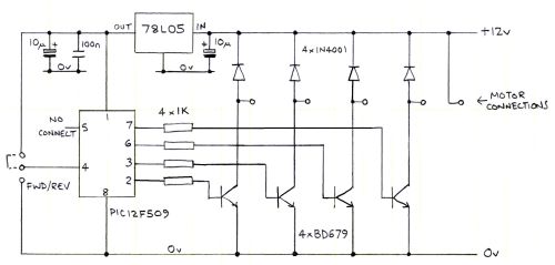
The electronics is very simple, all it does is cycle a four phase driver so the stepper motor is pulled to the next angle periodically. The timing is 25mS per step, the step angle is 7.5 degrees so the motor completes on full rotation in:
(360 / 7.5) * 0.025 seconds or 1.2 seconds. When the gearing is taken into account, the tank takes about 10 seconds to rock back and forth, five seconds rise then five seconds fall. The driver transistors are controlled by an inexpensive (about 50p) microcontroller and the program, written in Oshonsoft PIC10F BASIC is:
I initially thought of attaching the pivot to the MDF base board but trials exposed a small problem. As the gear turned, the peg not only lifted and lowered the tank, it also pulled it slightly from side to side and after a prologed time, the tank would have 'walked' far enough to fall off the base.
With dangerous chemicals in the tank I though this was not good. The fix was to think upside down and put the pivot on the underside of a plyboard platform. This also gave the opportunuinty to fit restrainers to ensure the platform and tank could never go astray.
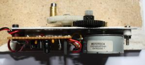
The motor and gears were mounted on a folded sheet aluminium bracket. This had seen life as a heatsink in an ancient stereo amplifer years ago but thankfully none of the holes in it clashed with the new ones I had to drill.
The motor was mounted first with its shaft protruding through the bracket, this made it easy to mark and drill the two fixing screws that hold it in place. With the motor cog fitted, the next step was to find the mounting centres for the two plastic gear wheels.
Define CLOCK_FREQUENCY = 4
Dim phase1 As Byte
Dim phase2 As Byte
Dim phase3 As Byte
Dim phase4 As Byte
phase1 = %010001
phase2 = %100001
phase3 = %100010
phase4 = %010010
TRISGPIO = %001000
direction:
If GPIO.3 = 0 Then Goto reverse
GPIO = phase1
WaitMs 25
GPIO = phase2
WaitMs 25
GPIO = phase3
WaitMs 25
GPIO = phase4
WaitMs 25
Goto direction
reverse:
GPIO = phase1
WaitMs 25
GPIO = phase4
WaitMs 25
GPIO = phase3
WaitMs 25
GPIO = phase2
WaitMs 25
Goto direction
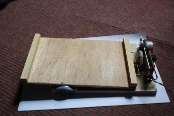
The base tilted each way. Note the position of the peg on the white cog wheel.
It should be self-explanatory, the '1' and '0' in the phase settings are the states of the pins driving the transistors and GPIO is the group name of the output pins on the chip. Although not used in this design, there was an unused input pin on the 12F509 so I used it to set the motor direction. Connecting it 5V or to ground will reverse the stepping direction. The compiled hex file is available here for those who do not have Oshonsofts compiler program. It is only about 120 bytes long. If you want the compiler, it is available from www.oshonsoft.com and is very inexpensive.
Stepper motors:
There are several types of stepper motor, the type I used is a five wire type. This has one common wire and four wires going to individual coils. To rotate the motor, the current through the coils is switched on and off in such a sequence that the rotor turns to centre its core to align the magnetic fields from them. In this design, you cannot use a four wire motor. These work in the same way as five wire ones but the current through the coils has to be reversed rather than just turned on and off. To reverse the current, a 'H-Bridge' driver has to be used which is somewhat more complicated and wasn't available in my 'junk box'.
The total cost of the agitator tank and hardware was under £10 (about 12 euros) of which most was for the plastic tank itself.