A step-up Voltage Converter for powering LNBs from 12V
This article first appeared in 'P5' - March 1996
Most LNBs are designed to work on supply voltages greater than 12V. Older ones prefer a fixed voltage of about 18V while newer ones use either 14V or 18V, the change in voltage being used to switch from horizontal to vertical polarisation or in some cases between low and high sections of the band. To power them from a 12 battery, a voltage booster such as described here is needed.
Several different types of DC-DC converters were tried with varying success but in the end this design gave best value for money. Flyback inverters gave higher efficiency under load but were more expensive and needed custom transformers winding. They also had the disadvantage that their off-load voltage would rise to unacceptable levels. Adding a voltage stabiliser would fix the regulation problem but at the expense of cost and complexity.
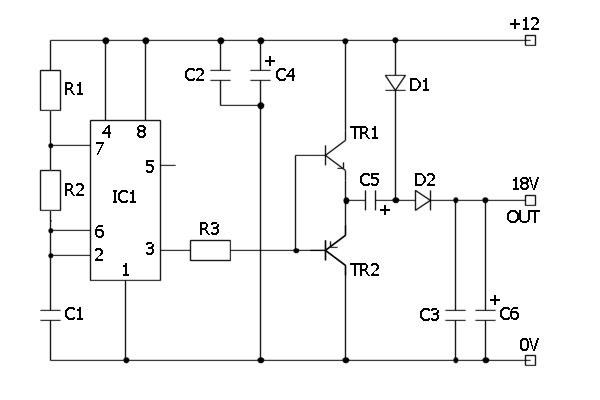
This unit uses a voltage doubling technique. A pair of diodes is used to steer the charging current to two capacitors. The first capacitor charges to supply voltage then the voltage is made to sit on top of the supply so its top end is at twice supply potential. The charge is then transferred through a diode to the second capacitor which acts as a reservoir for the boosted voltage. Theoretically, the output voltage is twice the supply voltage but in practice there are drops between the collector and emitter junctions of the transistors and across both the diodes. In the prototype the output was 22V off-load with a 12V supply and this dropped to 18V under a 150mA load. Input current at full load is about 300mA which makes the unit a very respectable 75% efficient. Under no load it draws about 15mA. The transistors do not need heat sinks, they run quite cool, even under full load, but they run very hot if the output is shorted out. I strongly suggest a 500mA fuse is wired in the supply line if there is any chance of a short occurring.
Parts list:
| R1, R2 |
1K |
| R3 |
100 |
| C1, C2, C3 |
22nF Ceramic |
| C4, C5, C6 |
100uF 25V |
| TR1 |
BD131 |
| TR2 |
BD132 |
| D1, D2 |
MUR120 (Shottky) |
| IC1 |
NE555 |
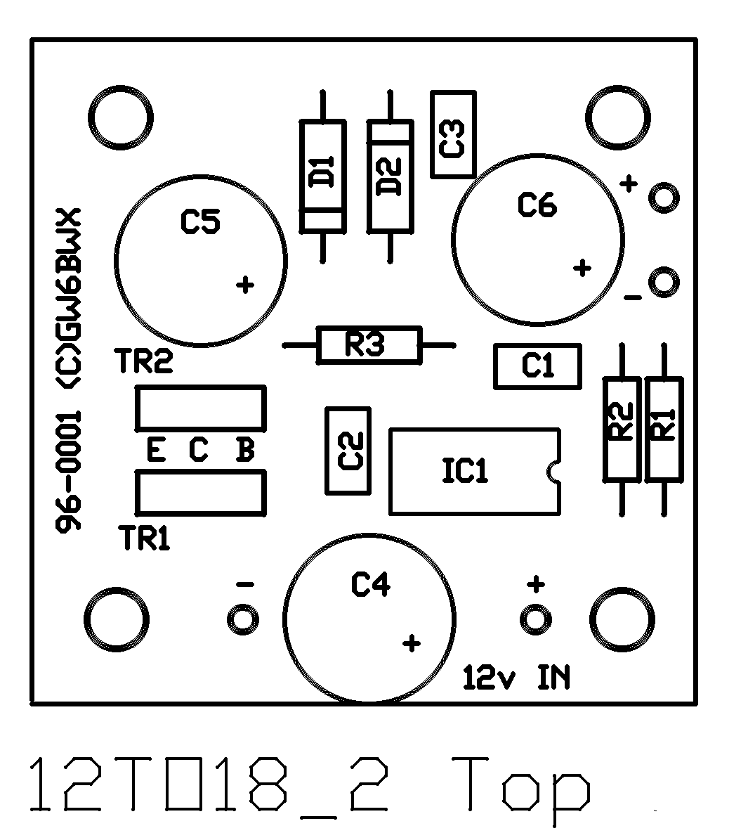
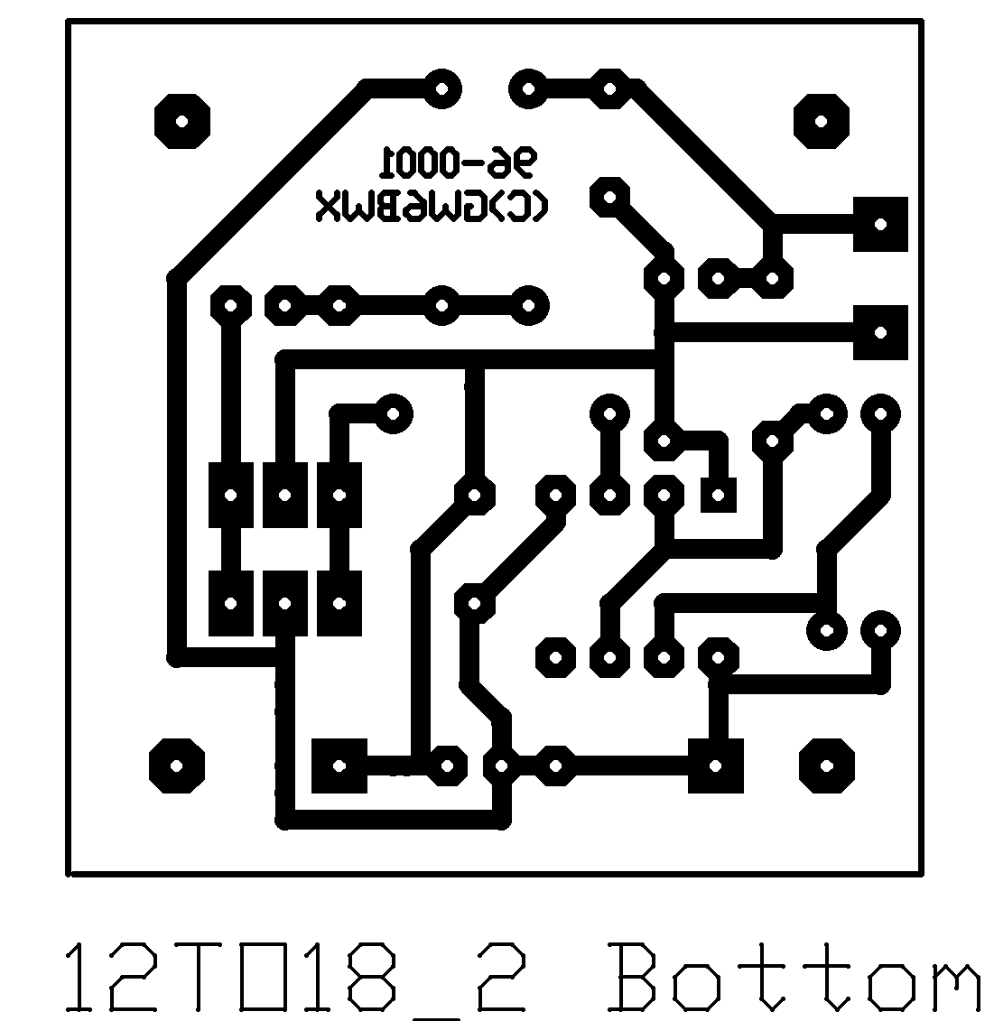
None of the resistor or capacitor values are critical but the diodes must be fast switching or schottky types, normal rectifiers will probably overheat and will seriously reduce the units performance. The PCB layout accepts electrolytic capacitors with 2.5 or 5mm pin spacing.