A Pulse Operated Ni-Cd Zapper.
This article first appeared in "P5" - March 1999
(the original article referred to showed a power supply connected across the cell via a push switch)
A recent P5 carried an article about bringing apparently dead Ni-Cd batteries back to life. This design uses a similar technique but instead of leaving the timing to chance, it gives a visual indication of the state the battery is in. I have concerns over the safety of the original circuit design, as it is quite possible for the switch contacts to weld, making it impossible to remove the charging current if the battery starts to overheat. Even removing the battery, assuming that is possible while it is hot, leaves the dangers that the rectifier could have gone short-circuit causing the reservoir capacitor to explode. To overcome all these hazards, this design uses short, controlled current pulses, which should be safe, even if left on for long periods with a shorted battery attached. An LED illuminates as soon as the battery has accepted charge to let you know its time to put the battery in a normal charger. This device repairs batteries, although it will also charge batteries, I strongly advise that a proper constant-current charger is used instead.
So what causes the battery to die in the first place?
Like most cylindrical cells, Ni-Cd batteries are constructed from a metal container, filled with active chemical compounds and a centre electrode suspended from a plastic bung at the positive end. In a healthy cell, the internal chemical reactions between the centre electrode and the casing produce about 1.25V across them. This is the voltage available to the outside world. As Ni-Cd cells deteriorate, the chemical filling starts to separate out and conductive paths between the centre electrode and case start to form. These are analogous to the formation of stalactites and stalagmites between the ceiling and floor of a cave. As these tracks grow they provide a leakage path which reduces the cells ability to hold charge. When the tracks completely bridge the electrolyte, the cell ceases to work at all and will usually measure as short-circuit between its terminals. In order to revive the battery, the short must be persuaded to break, rather like a fuse going open-circuit and preferably with its gap as long as possible.
The easiest way to blow the short is to force enough current through it that it heats rapidly and disperses the conductive path as widely as possible. Unfortunately, to produce enough current it is necessary to apply quite a high voltage, usually several times the cells natural terminal voltage. As the short clears it leaves the cell being overcharged by maybe 100 times its safe limit and this will cause further problems if left for too long. Having witnessed a small AAA cell launch itself 2 metres and embed itself in a wall, I cannot stress just how dangerous they can be!
To overcome the charging problem, the design described here uses very short high current pulses and enables a voltage monitor between them. Because the pulses are limited to 2 Amps and are only 1 millisecond long in every 10mS, the average power dumped into the cell is only about 0.25W, which is well within safe limits. During the 9mS between pulses, a monitoring circuit is turned on which will illuminate an LED as the cells voltage reaches about 1.1V. Trials with a selection of dead cells showed they all recovered within 5 seconds. Leaving the unit running for a long period only caused a slight warming of the battery.
Circuit Description.
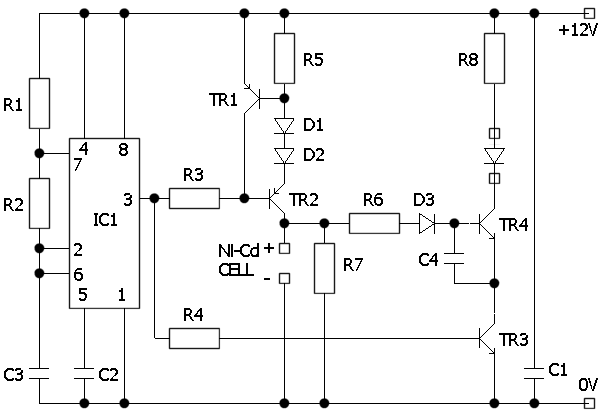
R1, R2 and C3 form the timing components for the NE555 timer IC. With these values the IC oscillates with a 10mS period (100Hz), the output pin going low for 1mS and high for the remaining 9mS. While high, it lifts the base pin of TR2 close to the positive supply rail, the two diodes in TR2s emitter ensure the base goes more positive than the emitter, therefore turning the transistor off. At the same time, TR3 is provided with base current and turns on, bringing its collector voltage close to 0V. If any voltage is present on the battery at this time it provides bias via R6 and D3 to turn TR4 on and light the LED. When the output of the NE555 is low, TR3 turns off preventing TR4 and therefore the LED conducting. TR2 turns on and allows current from the positive supply rail to reach the battery, this is the current that blows the short out of the cell. The current is limited to about 2 Amps by R5 and TR1. As current flows through R5 it causes a voltage drop that at a bout 0.6V makes TR1 conduct. As TR1 conducts, it provides an alternative path for TR2s bias current, limiting the current it can pass. An equilibrium point is reached with TR1 just starting to conduct, with R5 at 0.39R this is at about 2A. C4 is just a filter, because the delays inherent in fast switching circuits like this, very short pulses may occur during the on-off-on current transitions. These pulses are very short, typically only a few microseconds long. C4 ensures the LED doesnt glow dimly as these spikes occur.
| R1 |
120K |
|
C1 |
47uF |
| R2 |
15K |
|
C2,C3 |
100nF (0.1uF) |
| R3 |
270 |
|
C4 |
10nF (0.01uF) |
| R4 |
2.2K |
|
D1,D2 |
1N4001 |
| R5 |
0.39 1W |
|
D3 |
1N4148 |
| R6 |
10K |
|
TR1 |
BC212 |
| R7, R8 |
1K |
|
TR2 |
BD132 |
| IC1 |
NE555 |
|
TR3,TR4 |
BC182 |
The LED can be mounted off-board and can be any colour.
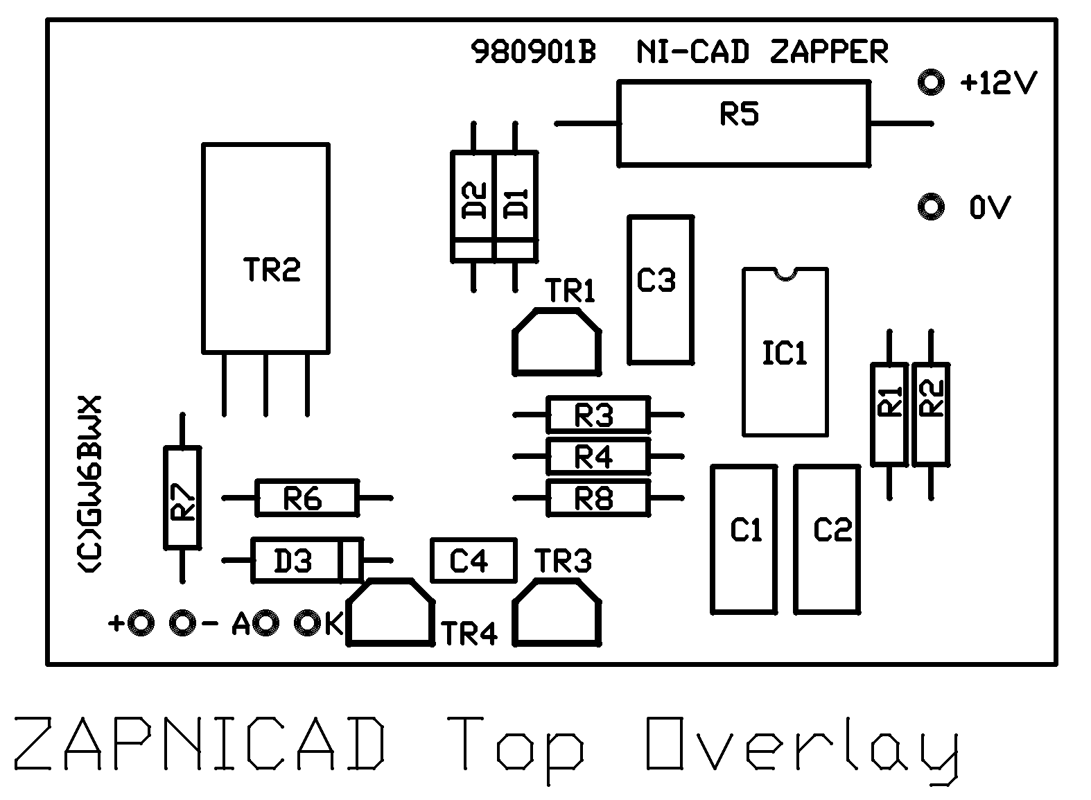
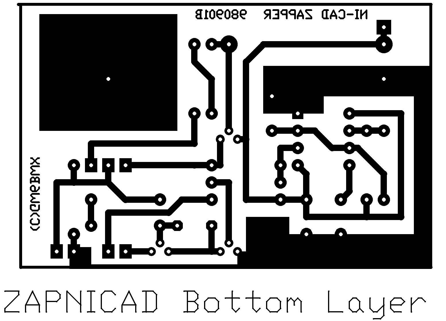
Construction:
A PCB design is provided but the layout is not critical. R5 should be rated at 1W and TR2 should have a small heat sink. The types of other components are not too important but keep to the stated values for the timing components or the 1:9 pulse ratio will not be accurate. D1 and D2 are rated at 1A current but actually carry pulses of about twice that amount. This shouldnt cause any problems as the short duty-cycle will prevent them overheating. Note that the circuit will draw short 2A bursts from the power supply, if measured it may appear to be much lower but the PSU must be capable of providing at least 2A at 12V.
Testing:
After checking for construction problems, apply 12 V from the PSU. The LED should NOT illuminate, except maybe extremely dimly due to leakage currents. Connect a capacitor of about 100nF across the battery connections, the LED should light but be fairly dim. Change it for a capacitor of about 10uF, this time the LED should be fairly bright. The capacitor is holding charge between the current pulses, simulating the action of the battery. If all looks OK, it should be safe to try the unit on real Ni-Cd batteries. Only use this design to rejuvenate single cells, never on packs containing more than one cell in series. Some batteries will be dead beyond recovery so I make no guarantees this design will work every time, but at a cost to build equalling about three new cells it could save you lots of money.
Click HERE for downloadable PCB files