PIC Program Development
This article first appeared in the December 2005 issue of P5
The family of PIC microcontrollers is now huge, there are several hundred different types although still all based around the same core functions. The different families are to cater for just about every users needs, some have just six pins while others have as many as 68, allowing them to control the simplest of circuits to highly complex ones. A wide variety of on-board interfaces are also available, ranging from single on/off pins to Ethernet ports and amazingly, despite some running at 20MHz or more clock speeds, they draw barely a few milliamps of power. The smallest 10F series devices draw less than half a milliamp while running and only nano-amps in sleep mode. With such a broad choice of built in facilities it is unlikely you would find a family member that doesnt have everything you need for any controller application.
Most of the newer PIC devices use FLASH memory. This is not an optical phenomenon! it is a kind of memory that retains its program or data even when power is removed from it. In fact most devices have a predicted memory life of 40 years, even after 100,000 reprogramming cycles. The fact that the chip can be reprogrammed is extremely useful, the chips effectively never become redundant, if the equipment using it becomes obsolete or is no longer needed, the chip can be erased and reprogrammed for an entirely new purpose. During program development it makes life ever so easy, if you find a bug or want to try something new you just wipe it clean and start again. Erasing and reprogramming takes just a few seconds and in many cases can be done without removing the chip from its circuit board.
Many of the smaller PIC devices have internal clock oscillators so that none of the limited number of pins have to be dedicated to setting their operating frequency. To make sure the on-board oscillator is tuned to the right frequency, they are calibrated during manufacture although it is possible to recalibrate them later if ever needed. Most devices with internal oscillators can still be externally driven or connected to a crystal for applications needing non-standard frequencies or extreme stability.
Now that all the components that used to be necessary around the device are built into it, you can for example make a Morse callsign generator in just two components - and one of them is just a resistor to lower the volume!
The mere thought of writing a program scares most people away from PIC devices. The fear of programming is unfounded; they are extremely easy to use. The most complicated, although most versatile method of programming is to write in assembly language. In this language, you write individual instructions for the processor to run. To be fair, there are only 35 instructions to learn and of these, probably half are rarely used. Because you have total control of the program flow, you can write very efficient and fast running programs. These days there are many tools available that make it much easier to code more complicated tasks by using what are called high level languages. These are computer programs that accept a more humanly readable set of instructions and convert them into one or more assembler instructions. When you use high level languages, you never have to see the underlying codes at all, everything at processor level is still there but hidden from you. Sadly, high-level languages seldom produce assembler code as efficiently as can be achieved by writing it by hand but the simplicity of the code far outweighs this disadvantage in all but the most critical applications.
If you want to play with PIC devices you will need two tools. One is the electronic circuit that actually takes the program from your computer and stores it into the silicon memory on the chip itself. The other is a tool to write the program in the first place. Not essential, but useful is a prototyping system that allows you to temporarily build a circuit around your programmed chip. This could be just to test a fragment of program or to verify a design before building it in more finalised form. The next sections look at what tools are available in more detail.
Programming the chip.
There are many designs on the Internet for DIY PIC programmers and also many commercially marketed units. Most of these can handle several families of PIC chips, the more advanced ones can handle them all. For the average experimenter, one that can handle the 16F84A, 16F628A and 16F877A will suffice. Beware of ones that cant manage devices with an A at the end of their part numbers as the programming methods used with these later devices is different to their predecessors without the A. The simplest designs on the Internet use just a few common components and connect to the computer printer port. Some are self-powering but most also need 12V or more from a power supply or mains adapter. After looking at many commercially available units I chose one of the ones from Quasar Electronics for myself. Quasar are based in Bishops Stortford in the UK. They market several versions of their programmers, some for parallel (printer) port connection, some for serial port connection and the one I chose which hooks up to a USB port. When choosing a programmer, I advise getting or building one with a ZIF socket for the chip being programmed. ZIF stands for Zero Insertion Force, the chip drops into the socket and is then locked in place by lowering a small lever. Raising the lever releases the chip. Conventional sockets where you push the chip against springy side contacts are cheaper but quickly wear out. I have one ZIF socket that still works after more than 10 years of hard labour! The USB programmer costs £39.95 with a conventional socket or £54.95 with a ZIF socket. The non-USB versions are cheaper. It is ready built and has support software which is periodically updated on the Quasar web site: www.quasarelectronics.com.
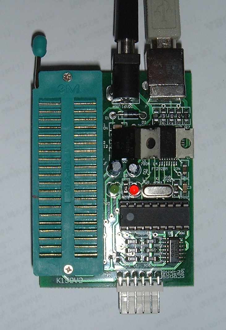
The Quasar Electronics 3150 chip programmer. It can program chips smaller than the 40-pins of the ZIF socket. The connections at the top are for power and USB. The pins at the bottom can be used to program chips which are already mounted on a PCB so they dont have to be removed and placed in the ZIF socket. This is called in circuit serial programming.
Writing programs.
As mentioned earlier, there is a choice of languages to write programs in. For the smaller devices with little memory, it is probably easiest to write in assembly language. High-level languages tend to add extra instructions that eat into valuable memory space. If more than about 1Kb of memory is available, and most PICs have at least that much, you should consider high-level languages for their simplicity of use. Generally, the word assembler is used to describe software that converts individual human readable instructions to PIC machine code on a one-to-one basis and the word compiler describes software that converts high-level language instructions to possibly hundreds of PIC machine codes.
If assembly language is your choice, you can do no better than use the PIC manufacturers own program writing package called MPLAB. The current version is 7.22 but new releases come out every few months to add support for new chip types. MPLAB is a big program, weighing in at about 80Mb when installed but it does handle all the PIC varieties and it includes an editor to write the program and a powerful simulator that lets you run the program from within MPLAB to make sure it behaves as expected before committing it to a real chip. You can download MPLAB free of charge from www.microchip.com.
If you prefer the convenience of high-level languages, there are two common ones available; they are BASIC and C. BASIC is a simple language, originally written for beginners back in the 1970s but now adapted to work with PICs as well as PCs and larger computer systems. The C language is a little more complicated to learn but is far more powerful and lends itself to being more convertible to assembler instructions. Both languages introduce pre-built functions that are not normally present if you work directly in assembly language. These pre-built functions are a collection of assembly instructions coupled to a method of retrieving and passing back data. You pass data to the function and get data back from it, the function doing something useful with it in the middle. For example, to illuminate the digit 5 on a seven-segment display connected to the PIC in assembly language you would have to set the PIC pins connected to the appropriate LED segments to a high voltage and the PIC pin joined to the LED common pin to a low voltage. In a high-level language this might be written simply as SetLED(5). The outcome is the same but the high-level code is easier to write, understand and if necessary, edit later. Another strength of high-level languages is that you can make your own functions either from assembler instructions or by combining other functions together. Quickly, you stop thinking of making pins of the chip go high or low and start thinking in terms of what your program is intended to do. If it is a clock telling the time of day for example, you are more interested in knowing if midnight has been reached than the dozens of numbers in the PICs working registers. High-level coding gives you that degree of isolation from the inner workings of the chip.
Programming in BASIC.
Several companies market PIC BASIC compilers but after looking at all of them, one stood out from the crowd for its simplicity of use and its low price. Written by Oshonsoft it is called PIC Simulator IDE and can be downloaded from www.oshonsoft.com. The IDE part of its name stands for Integrated Development Environment, meaning you can do everything within the program to write, debug, simulate and test your work. Although this program doesnt have an operating manual in the normal sense, it does give examples of how to use each of its commands and the graphical layout of the various display windows makes it very easy to understand. When a program has been written, it can be tested using a selection of commonly attached devices such as LCD displays, LED displays an oscilloscope and a waveform generator. All of these devices appear in their own windows on the computer screen and have setup options to allow you to connect them to whatever pin you want on the PIC being simulated. When the simulation is run, the main program window shows the sequence of instructions being run and the contents of all the registers inside the chip, windows showing the attached devices update as the PIC sends signals to them. You can run the program at different speeds so you can see whats happening in slow motion and you can single step your program one instruction at a time to see what effect the instruction is having. I even loaded programs written in an entirely different language into PIC Simulator IDE and it correctly emulated their operation. This is one of a very few programs that can read, reverse engineer and run programs from other sources. I find this feature alone invaluable because it lets me double check the operation of programs when I no longer have the original source language files to work from. Oshonsoft charge 29Euros (about £18) for a license to use the program but it can be evaluated for a limited time free of charge. They also sell similar products for other types of processor such as the Z80 and 8085 devices
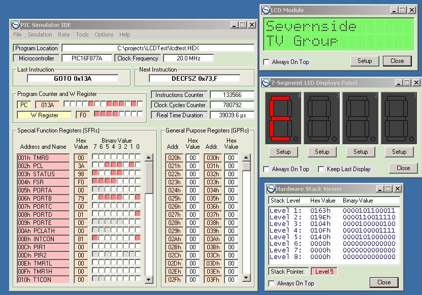
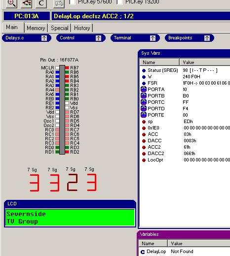
Oshonsofts simulator with the program, LCD, LED and stack windows open. These are just some of the windows you can open to look at the inner workings of the program.
The pink dots in the program window are a map of individual bits turned on in the processors internal registers.
Programming in C.
As with BASIC, several companies sell C compilers. Most are more expensive than the BASIC counterparts but the language is better structured and allows more efficient code to be generated. I evaluated several compilers but decided to go with WIZ-C from Forest Electronic Developments in Hampshire. They sell WIZ-C in various forms from the Lite version at £35 which only works with a limited number of PIC types (the common ones) through to the Pro version at £100. The Pro works with almost all PIC types and can even simulate several PIC types connected and talking to each other while each runs different programs - complicated stuff! WIZ-C is a complete program writing solution, it lets you type your program into its editor by hand or guided by an auto code facility which drops applicable chunks of code into place for you. It also features an application designer which is a wonderfully useful tool that allows you to pick from a selection of commonly used elements and drop them into place on a picture of the chosen PIC. After doing this you connect the appropriate signals from the element to the pins of the chip by clicking on them and not only does the screen show how everything is wired up, it also writes the appropriate lines in the program for you. You still have to glue the bits of program together to achieve your aim but much of the graft of telling the program what connects to what is done for you. WIZ-C has an excellent simulator and like the Oshonsoft program, it lets you build a circuit on the screen and see how it will behave in real life. It differs from Oshonsofts simulator in that it allows you to create stimulus files in which you specify actions to perform at different times. These actions could for example be send a serial byte at 9600 baud to pin 9 after 3 seconds and while running, that is exactly what it would do. It allows you to mimic real life events that your final design might encounter and see how your program reacts to them. WIZ-C also has more devices to connect to the simulation than Oshonsofts program. To be fair, Oshonsoft provide details of how to make your own devices to expand their product but experience with other programming tools is needed to do this. Forest Electronic Developments also sell an assembler program and similar product for AVR processors. They also have a support forum for users on the Internet. Their web site is www.fored.co.uk.
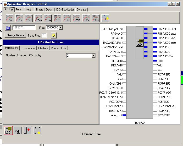
The Wiz-C
Application
Designer.
One corner of WIZ-Cs simulation screen. The image is a representation of the pins of the 16F877 being simulated. The colours show whether the pin is an input or an output and the logic level on it.
The numbers in the window on the right are the contents of some of the processors registers. Clicking on the oval buttons allows different selections of data to be shown.
Program examples:
This is just to show you how simple it is to put a message on an LCD connected to a PIC16F877A in BASIC and in C. In both examples, some of the preparatory code is not shown, only the part that actually writes to the LCD is.
In BASIC:
Lcdcmdout LcdClear 'clear LCD display
Lcdout "Severnside" 'text for the line 1
Lcdcmdout LcdLine2Home 'set cursor at the beginning of line 2
Lcdout "TV Group" text for line 2
In C:
ShowMessage()
{
LCDClear(); //clear the LCD display
LCDString("Severnside"); //top line message
LCDPrintAt(0,1); //cursor to bottom line
LCDString("TV Group"); //bottom line message
}
As you can see they are very similar and both quite understandable.
Prototyping systems:
If you are confident that your program will work, you do not need a prototyping system. If like me you write programs that rarely work first time, prototyping can save hours of frustration and anger. Sometimes, no matter how many times you check and double-check your work, you overlook the simplest of things. Frequently this is because you did not predict what signal might be present on a chip pin or you didnt appreciate a resistor was needed between a pin and the circuit it connected to. The only way to be absolutely sure is to build real hardware to try it out. The trouble is, you can easily get into a loop of hardware change causing a software change causing a hardware change again and so on. In order to try the design while still tweaking values and software, you need a method of rapidly building hardware in such a way that it can be modified easily, this is where prototype boards come to the rescue. They typically have a patch board area on which you build your circuit and link pins so you can connect to the PIC. Some have other devices on them to make it easier to hook-up some of the more commonly used circuits. Many prototyping boards are available but the one I chose for myself because of features and value for money is from a Hong Kong company called Momentumfire. Their board has a ZIF socket for a 16F877 processor, a 4x4 keyswitch array, a two-line LCD, four seven-segment LEDs, an RS-232 serial port for connecting to a PC, a buzzer, a real time clock chip (time of the day clock) and a memory chip. The memory is advertised as being an 8Kb device but my board came with a 32Kb device, perhaps I was just lucky! As well as the main board, a separate patch board was supplied, this uses spring contacts to connect component legs without needing to use solder. The board is type MFC-1027 from www.momentumfire.com/258.html and costs about £40. This is about half the cost of buying the parts alone in the UK but there may be some variation in price as exchange rates vary.
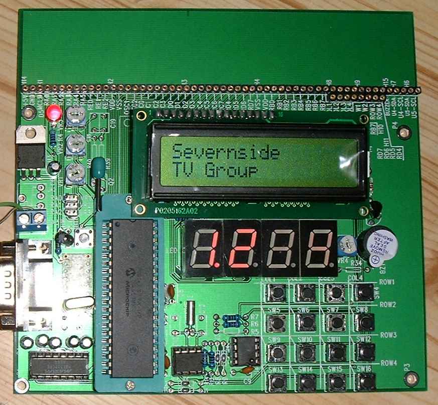
The prototyping board from Momentumfire. Shown here running the same program as simulated by WIZ-C and Oshonsoft programs. The LEDs were actually showing 1.234 with each digit shown in turn but the camera shutter was too fast to see them all.
The pins along the top row give access to all the processor pins and other signals necessary to connect to the board.
The prototyping system will normally run at full speed, it is after all a normal running circuit despite the temporary construction method. Beware though that even on the fastest PCs, a simulation will run much slower than real time. WIZ-C is actually quite fast at simulating a real environment; Oshonsofts simulator is considerably slower. They do however, agree exactly on functionality and on their assessment of execution times if real time could be achieved. Both programs accept code written in assembly language as well as their high-level counterparts.
You have seen here just a small sample of tools available to PIC developers. I use all the programs and the prototype board described here. The programs each have their strengths and weaknesses but together they make a potent collection of programming tools. I hope I inspire you to try your hand at using these versatile devices.