Remote control of a relay switching unit using DTMF (Dual Tone Multi-Frequency) commands.
note: DTMF is the system used in standard tone dialling telephones.
This article first appeared in "CQ-TV" magazine, issue 186.
I was asked to design a unit that could be used to control monitoring equipment at a TV repeater site. It had to accept commands sent as DTMF tones over the repeaters audio channel and be able to switch either AV signals or power supply feeds at currents up to 1 Amp. The switching requirements left no option but to use relays and the cheap and easily available BT53 style was chosen. As these are two pole relays but only one was called for, the other was put to use to drive a monitoring LED. The LED is illuminated when the relay is energised. It is simple to modify the the wiring to allow both poles to be used if the LED facility isnt needed.
The design specification stated that the unit should co-exist with other MF controlled equipment, specifically, the single MF tone pair commands that GB3XG used and the sequence of four tones that GB3ZZ used. When I wrote the operating system for GB3ZZ over a decade ago, I deliberately left a gap in the valid command sequence "for future developments. In hindsight, this was a good idea as it left space for commands this unit could use. The range of MF commands available is *50# through to *59# although this can easily be changed by modifying the source code and re-assembling the PIC program. Unfortunately, GB3XG uses single tone commands so for example, keying *52# would be seen as four individual instructions that could have left the repeater performing unwanted actions. To overcome this problem, the audio feed to the repeater had to be disconnected as soon as the * was seen and then reconnected after the # was received. One of the relays is used for this purpose. The audio is looped through the board and interrupted for the duration of the command sequence. All the other relays have accessible changeover switch contacts (note: SK6 and SK7 have reversed pin-outs) and are available for general-purpose use.
To make the unit as versatile as possible, the relays operate in different ways. Some are selected as one of four, some are turned on with one code and off with another and one relay has a timed period before switching itself off.
The actual commands are:
*50# turns relay 8 on, 5,6 & 7 turn off,
*51# turns relay 7 on, 5,6 & 8 turn off,
*52# turns relay 6 on, 5,7 & 8 turn off,
*53# turns relay 5 on, 6,7 & 8 turn off,
*54# turns relay 4 on,
*55# turns relay 4 off,
*56# turns relay 3 on,
*57# turns relay 3 off,
*58# turns relay 2 on,
*59# turns relay 2 off. Relay 2 also switches off after 5 minutes have elapsed.
Relay 1 is used to interrupt the audio loop through.
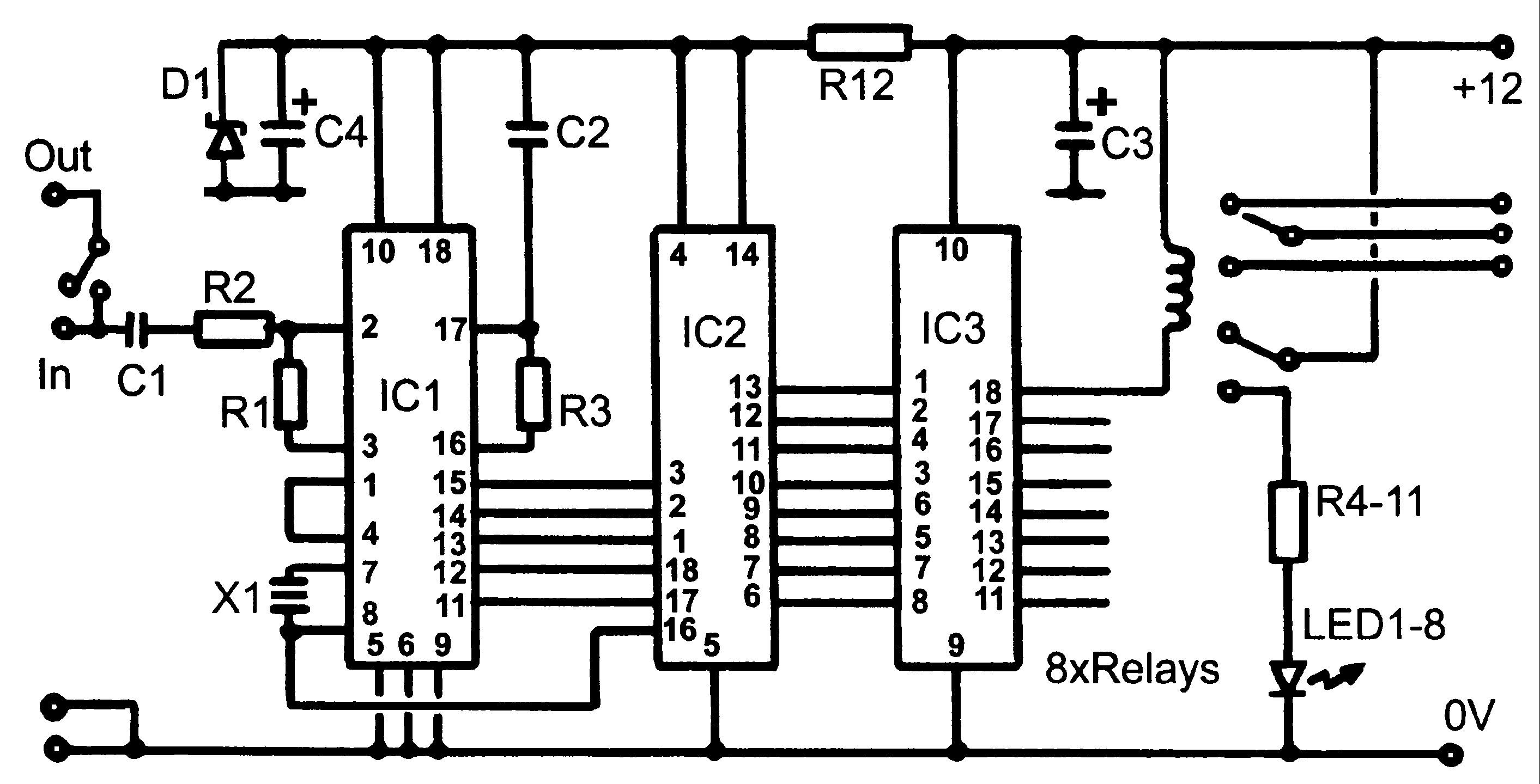
Circuit Description.
The industry standard 8870 chip performs the decoding of audio tones to a binary number. The chip not only filters the audio but also uses a clever decision process to check that both tones are present for at least 40mS. When it has decided that a genuine MF signal has been received it decodes it to a binary number and signals it has done so by raising a tone detected (strobe) pin. The binary number and strobe signals are fed to the 16C84 device, which reads the signals in through its RA (port A) pins. It checks to see if the tone corresponded with the * digit and if so, it disconnects the downstream audio by operating relay 1 then starts a five second time-out counter. If the following digits are in the 50 to 59 range and received within the five seconds, it drives the appropriate RB (port B) pin high or low to operate one of the relays. If the 5-second period runs out before the remaining digits have been received, it purges any that did get through and turns the audio back on again. This technique lessens the chance of an incomplete sequence being finished inadvertently at a later time.
The RB pins are capable of driving the relay coils directly but would be pushed close to their limits to do so. To ease the strain on them, a ULN2803 driver IC is used which also has the benefit of having clamp diodes on each output. This eliminates the need to add eight diodes, one across each of the relay coils to snub any back voltage as the relay de-energises. The remainder of the circuit consists of LEDs and current limiting resistors to show which relays are active. These can be omitted if desired. The unit runs on a 12V supply but can be modified to run on 5V if the relays are replaced with ones having a 5V coil rating. The D1 can then be omitted and R12 replaced with a link. I have not tried this myself, it is possible that current spikes from the relays might propagate through the supply line and upset the PIC or 8870.
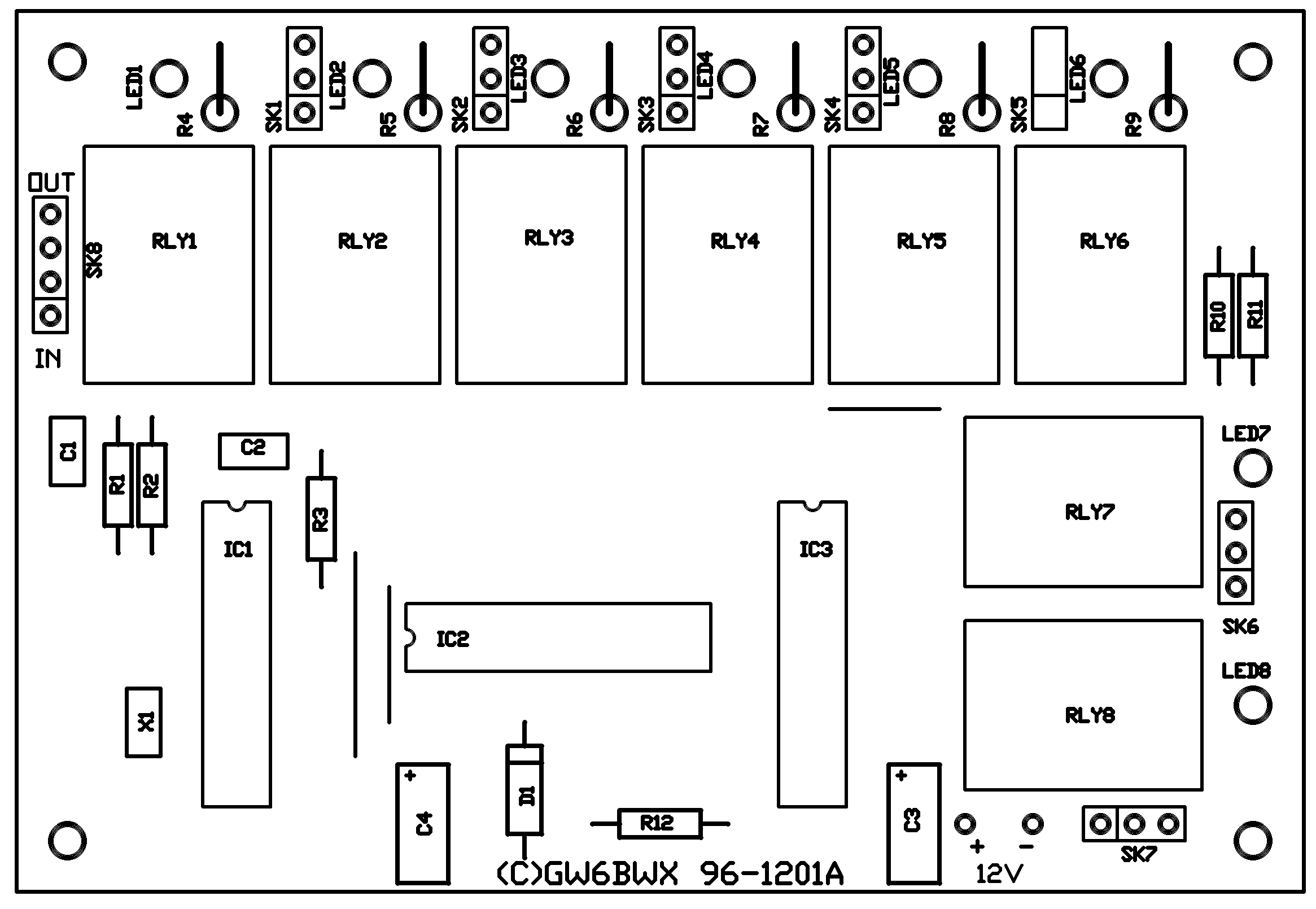
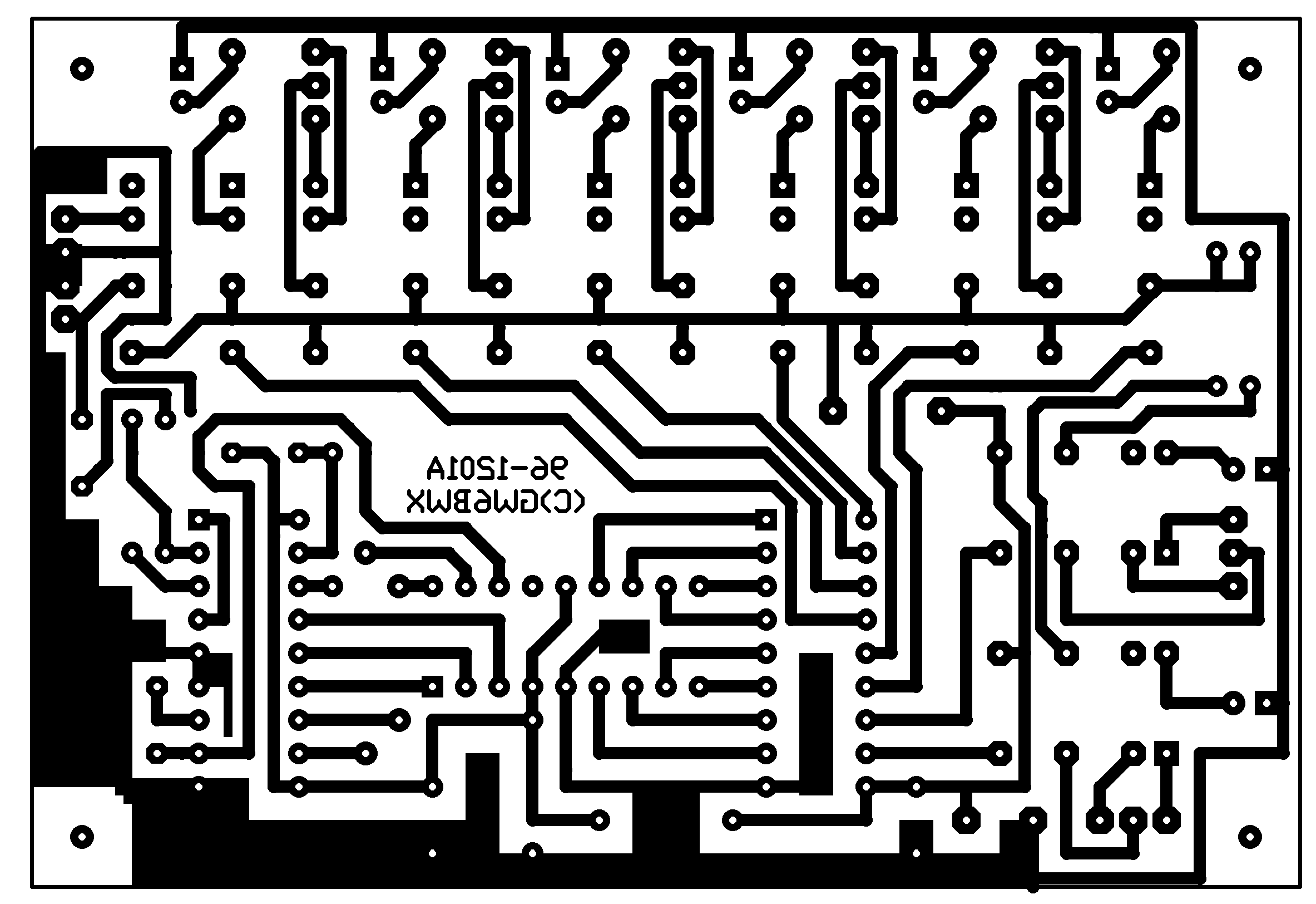
Construction.
See the web page on making PCBs for more details on making your own board.
Apart from the usual static precautions, there isnt much to advise about building it. The 16C84 must be programmed before use and be set to its XT oscillator configuration. It actually gets its clock from the generator inside the 8870 but setting it to XT mode will ensure its own on-chip oscillator doesnt try to start up. The original unit used 0.1" Molex type connectors but Veropins or even just soldering wires to the board is acceptable. Remember to connect the audio input and output pins the right way around or the unit will always disconnect itself and never hear more than a single tone!
Parts list:
| R1, R2 |
100K |
| R3 |
330K |
| R4 - R11 |
1K |
| C1, C2 |
100nF (0.1uF) |
| C3, C4 |
10uF / 16V |
| D1 |
BZX88 C5V1 |
| X1 |
3.579MHz |
| IC1 |
MV8870 |
| IC2 |
PIC 16C84 |
| IC3 |
ULN2803A |
| LED1 - LED8 |
Red LED |
| RLY1 - RLY8 |
BT53/3 (12V) |