Analogue vs. Digital ATV.
What really are the pros and cons?
This article was first published in CQ-TV issue 202
ATV has been with us for a long time. Indeed the BATC has itself been around for 54 years, thats almost all the time recognisable television has existed.
During this period the design and manufacturing techniques used in ATV have developed more or less in parallel with those of commercial operators. The picture quality we strive to attain today is that of the broadcast companies. Go back a few years, not all that many, and the picture quality we perceived to be excellent would today be described as adequate at best. Take a look at some of the earlier BBC recordings, especially those in the first days of colour TV and they look decidedly P4 by modern standards. If my ATV signal was as bad as some of the first colour broadcasts I would seriously consider there being a fault inside my transmitter. The commercial stations have always been the benchmark by which we perceive our own standards. As they have improved, so have we.
The problem with improvement is that there is a diminishing return on investment as the quality increases. To go from nothing to good is much cheaper than going from good to excellent.
Lets look at commercial stations first. The only practical solution to the problem of increasing picture quality using analogue transmissions is to widen the bandwidth they occupy. This is a scientific fact. By virtue of the band planning set out at the time the UHF broadcasts were proposed, the number of available channels was severely limited. The plan only made provision for four TV channels per region and that restriction still applies today. It is to the great credit of the ITC that not only have the four original channels been squeezed into the band but also a fifth analogue station, 5 and six digital multiplexes as well. Considering there are several hundred broadcast transmitters up and down the country that, in theory at least, dont overlap coverage areas, that was no mean achievement.
So, being confined to a limited band space and at the same time needing to bow to public demand for more entertainment, what options were open? The first and most obvious step was to spread into a second band and carry on making the same type of transmission. This happened in the early 80s with the commencement of satellite relays. The broadcasters saw satellite as a huge wide-open space to sprawl into and thats just what they did. The first satellite broadcasts were analogue, I believe some of them used amplitude modulation but for technical reasons, particularly because of the limited power resources and amplifier linearity, almost all opted for frequency-modulated transmissions. With all that empty band space there was no longer such a need to keep the transmission spectrum so narrow so typical bandwidths of satellite systems were in the order of 25 to 30MHz. For the UHF stations the limit was under 8MHz. In the early days (anyone remember when there was only one Sky channel?) things were fine, however, as the public demand still kept growing, the bands became more and more populated and we went right back to square one again. Of course, satellite has the great advantage of using highly directional receiving dishes so the actual number of satellites could be increased as long as they stayed more than a few degrees apart in the heavens. This allows for a very large number of channels but makes receiving them all a big problem for the consumer who would need several fixed dishes pointing to individual satellites or a steerable dish that could be moved to select one of them at a time. Apart from a few enthusiasts who have the ability to erect and control such systems, they are not suitable for the general public.
Lets recap:
better pictures = wider signals
wider signals = less will fit in the band
more bands = more equipment is needed
satellite = more band space but still limited.
more satellites = expensive dish or array.
So how are the needs of the public met? Compromising quality at a time when large screen TVs were starting to hit the market wasnt a sensible option. The bigger the screen is, the more obvious the limitations of quality become apparent. Opening up more bands at a time when other users were queuing for frequencies, particularly mobile and telephone services, was also not a viable option. There was an attempt to cable the whole country so all the band space could be released but that has slowed to a crawl for financial and geographical reasons.
The most cost effective way forward is to utilise the same technique used by computers to compress digital images so they take less storage space. Without the quality suffering disagreeably, it is possible to shrink images, photographic or from a video source to a much smaller size, typically 20% to 30% of their original proportions. The big problem is the image is no longer in a format that can be viewed on a normal TV. As it is now a bundle of digits, it takes a computer to make sense of them again. Compressing the information does not in itself help us; we need to make use of the space left over, the remaining space from its previous dimension. As we are now in the digital domain, the space can simply be filled in with another picture. This could be more from the same picture stream or could be from a different source entirely. Just compressing and sending a single picture would waste the bandwidth just saved. It isnt possible to send the next frame of video either as it probably wont have left the camera yet!
So we now have some spare capacity in the bandwidth. Bearing in mind that the prime motive for doing this in the first place is to relieve the pressure from an overcrowded band. It makes sense to fill the freed-up space with another station. Hey presto!, two stations in the space that used to hold one. The overcrowding has suddenly halved. In practice the compressed pictures are generally quite small and the bandwidth is still quite wide so up to eight stations can be squeezed into one channel. This process is called multiplexing and the component signals can be control information as well as picture streams. For example, the Freeview transmissions on UHF and the Sky broadcasts by satellite both carry program guides and have the ability to remotely update the software running in the receiver.
As well as reducing spectrum usage, digital TV has a big financial advantage for the broadcaster: The cost of transmitting is spread across all the channels. Now, a single transmitter, with its single running cost can do what would have required up to eight transmitters before. A considerable saving is made.
Theres an old saying: you dont get owt for nowt, and it is as true for digital TV as in everything else. The drawback is of course that picture quality suffers and the complexity of equipment is vastly greater than with analogue. Im sure most professional broadcast engineers would agree that you cant beat the quality of a well set-up analogue signal. Few would also fail to recognise a digital picture. When you look closely there are several telltale features of a digital picture that give the game away. The two most obvious are pixelation or blockiness and compression artefacts. The pixelation can be caused by two things, a transmission error because some of the bits in the digital data stream were corrupted or lost or simply by insufficient bits being available to convey the complexity of picture. Take a close look at a digital channel showing fine background detail, a choppy sea or grass on a sports field for example, and you will see it take on a rather fuzzy appearance, often showing a rectangular pattern over the picture. The effect is more obvious on darker scenes where the numerical value of bits representing the brightness is smaller. Transmission errors are seen as misplaced blocks of picture or brief pauses in the picture being redrawn. The compression artefacts are false regions of the picture that are wrongly extracted when the compressed picture is brought back to full scale. These are clear to see if you look closely at still text, particularly against a light background. Around the edges of the characters you will see a border with a rope like pattern in it. It is always there and around any region of the picture where a step in colour or contrast occurs but text shows it up best.
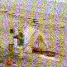

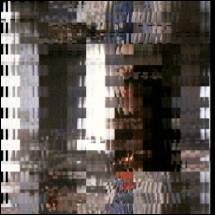
Figure 1 shows the 4KW analogue transmission of Channel 5 received from transmitter at BlaenPlwyf
Figure 2 shows the digital transmission from the same mast and with the same receive antenna. This is one of 6 channels in the multiplex with 2KW total ERP.
Figure 3 shows an extreme case of a decoding error. Here the information was incorrectly decompressed and blocks are misplaced in the picture.
To minimise the effect of bit errors there are several protection mechanisms added to the video data. Digital error correction is nothing new, without realising it was there, you would have used Hamming bits and parity bits while watching any Teletext page. In their simplest form, these protection bits are used to periodically add confirmation that the data is intact. Parity is a single bit applied at the end of a byte to make the total number of 1 bits in the byte either odd or even. If even parity is being used and an odd number of ones are found, the byte must contain an error. Parity cant fix the error and its weakness is that it can be fooled by more than one error making the number of ones appear correctly as odd or even. Hamming bits go one stage further; a parity bit is added after each data bit, the result is a byte twice as long because it alternates between real data bits and their parity bits. Each Hamming bit represents the parity of all the bits preceding it and by the magic of mathematics (actually a few XOR gates) it is possible to see where the error has occurred in the byte. Given that each bit can only be a zero or one, it isnt difficult to work out which it should be if its wrong!
Even these techniques are too weak for digital TV, much more powerful error trapping and correction is needed. The method actually used is very complicated and involves polynomial checksums, Reed-Solomon and Vitterbi encoding. At the end though, what counts is that even a severely tortured signal can come through unscathed. If not completely unscathed, at least the apparent damage is well hidden. There are numerous web pages that explain how TV signals are prepared for transmission and recovered at the receiving end. I wish all readers lots of luck trying to fathom such depths of mathematics though; nothing Ive found so far is for beginners.
The root cause of errors is the variability of the transmission path between transmitter and receiver. It is really easy to feed a clean signal down a length of coax, try doing the same over tens or hundreds of kilometres, especially across hilly terrain and you soon witness every kind of signal distortion known to mankind. With analogue signals the degradation shows as snow or ghosting, depending on strength and multiple signal paths respectively. The eye can tolerate reasonable amounts of these effects and the brain can selectively ignore them so the viewing experience is not so seriously impaired. Digital signals do not have the luxury of gradual quality loss. Instead of the subjective picture quality falling, the integrity of the data falls and there comes a point where it can no longer be interpreted as a picture at all. Try to imagine an analogue picture with a ghost as a main signal and delayed version of itself added together. Where there may have been a bump in the waveform at the source, it arrives with two bumps at its destination, the original and the ghost. Now visualise the same happening with a stream of binary ones and zeroes, when the delayed signal is added it can completely change the pattern of bits and turn the information it carries into nonsense.
Three main types of digital transmission are used: DVB-C, DVB-S and DVB-T. A system called ASTC is also used in the US. These are broadly similar but in view of the different signal paths they are intended for, they use different transmission modes. DVB-C is for use on cable distribution networks and it optimised for use where signal strength is likely to be high and stable but there may be some minor reflections due to cable terminations being imperfect. DVB-S is for satellite broadcast, such as those from Astra. It is optimised for low signal strength where electrical noise may be present but the path is clear of reflections. DVB-T is for terrestrial transmissions where signal strength and multi-path distortion are both likely to cause problems. For the DVB-C and DVB-S systems the transmissions are modulated using QPSK, which in simple terms is a method of splitting the bytes into small groups of bits and converting these to a particular amplitude and phase. The pattern of amplitude and phase are recognised at the receiver and the data bits are reassembled into the original bytes. QPSK is short for Quaternary Phase Shift Keying. Of course, phase shifts along the transmission path can really screw this up which is why it is used for satellite TV where the path is line-of-sight. For terrestrial TV where DVB-T is utilised, QPSK is still used but the signal is then fed through an OFDM modulator. This cleverly spreads the bits across a number of closely spaced carriers in such a way that even if a large proportion of the carriers suffer interference, the modulation can still be recovered. Again the mathematics behind this technique is very complicated. OFDM stands for Orthogonal Frequency Division Multiplexing.
Thats enough on what the commercial stations do, now lets look at how ATVers can make use of digital TV.
Firstly, and contrary to the majority of comments I get in my email every day, digital is not more complicated and not necessarily more expensive than analogue. Just as with analogue, there is no upper limit on what you can spend, but how little you spend depends on your ingenuity more than on your bank manager. Admittedly, some of the encoding circuits will have to be in complex chips but these are no more expensive than a PA transistor that can run a couple of watts on 24cm. There is the advantage that the maths has been done by someone else and all you need to do is utilise it. If that sounds like it takes the fun out of it, may I ask when was the last time you designed a transistor?
When you look closely at a digital transmitter and receiver and compare them with their analogue counterparts, they have much more in common than you might first imagine. The oscillator and RF amplifier sections are the same, the video amplifiers are the same the PA is the same and the power supply is the same. The only difference is in the modulator and demodulator. Given that these are the bits that are pre-designed for you it probably make digital easier to build than analogue.
The criticism that digital is perfect or nothing at all, referring to the critical signal level where errors can no longer be tolerated is understandable but somewhat flawed. Although it as absolutely true that a digital signal may be missed completely when it is only marginally below the threshold, that threshold is actually about the same as P2 in analogue terms. In other words, what digital cant resolve would also be stretching an analogue system to its limit. Ive also seen a rather silly comment that you cant line-up a receive antenna on a weak digital signal because you cant see where the signal peaks. Well, for the past 30 years Ive used an S meter, I suggest you give it a try. In fact most commercial digital receivers have a built in strength meter and a signal quality meter too. The quality is assessed by monitoring the BER or Bit Error Rate. This is the number of errors that have been corrected. A lower BER means a cleaner signal, its probably as near to a P grade meter as we will ever get. If you have Freeview or Sky digital, look at the installation menu and you will see the strength and BER displayed as bar graphs on the set-up screens.
Now lets turn to some of the operating advantages of digital.
For as long as I can remember, the major drawbacks to using the 70cm band for ATV have been the inability to use colour and inter-carrier sound because of insufficient band space and the problem of causing interference to other band users. Digital signals use the bandwidth more efficiently and it should be possible to transmit not only colour and sound but also data and additional sound channels without stepping out of band. In addition, the power spectrum is more evenly distributed, especially if OFDM is used. Although the potential for causing interference is still there, for a given ERP there should be on average less power per unit of bandwidth than an analogue signal would exhibit. Additionally, any interference would be heard as random noise rather than the obtrusive sync buzz that analogue ATV inflicts.
On the higher frequency bands the capacity for carrying more data, more pictures or higher quality pictures is even greater. Imagine an ATV repeater that has, for example, receivers in the 70cm, 24cm, 13cm and 3cm bands. If signals from each of these were multiplexed they could all be retransmitted over a single digital channel. As each channel would have its own ID number, a digital receiver could pick whichever input signal was desired for viewing. For example, channel 1 could be the picture from 70cms, channel 2 from 23cm and so on. Although the repeater would only broadcast on one frequency, it could cross-band repeat from several bands at once.
Some ATVers get their kicks from squeezing the most out of a limited RF carrier, some from striving to attain a perfect picture. I believe digital goes some way to catering for both of these camps. Certainly, the relatively small picture degradation as signals get weaker will please the quality chaser who no longer has to fight through snow. The better sound and stereo capability should also please these operators and add the challenge of bettering their audio techniques to the hobby.
For the web-heads out there, as all their information is already digital, it should be relatively easy to interconnect with computers, modems or whatever. It would even be feasible to run repeaters in different modes altogether. Think of a repeater carrying ATV and a high-speed packet link simultaneously or maybe acting as a proxy server to allow Internet access at high speed.
Think of the advantage of sending your regular mug shot with a test card and a page of station information at the same time.
So what equipment is available for DATV? Well, receivers are already available, both for QPSK and OFDM modes. In fact, the demand for economical domestic equipment has prompted several manufacturers to develop ICs that are virtually self-contained receivers. Zarlink for example, produce single chip QPSK front-ends and single chip OFDM front-ends. They also make a complete receiver on a chip but this is in a 388-pin BGA package that, from an amateur point of view, is impossible to utilise. BGA, or Ball Grid Array is a chip package where instead of through pins, connections are made directly to solder pads on the underside of the chip package. Solder balls form a bridge between the PCB pads and the chip pads; there are no legs at all. With suitable tuning arrangements and digital to analogue conversion, these chips will make very high performance receivers. For the black-box people, a Freeview receiver (£99 or less) with an up or down converter in line with its antenna socket makes an excellent OFDM receiver. For QPSK there are dozens of receivers on the market. Sadly, the fixed symbol rates of the BskyB satellite receivers make them unsuitable but many other units are available as DVB set-top boxes. I recently sought advice from BATC member Tony Wise at Wyzcom about which receivers were most versatile for amateur use and he recommended the Humax CI-5100. I should point out that as well as being an active ATVer; Tony is also a Humax dealer. His advice led me to buying an excellent receiver. It arrived just in time to pick up an ATV test transmission from Sweden and it should be fully capable of receiving terrestrial QPSK ATV transmissions as well.
Transmitters are at the moment the big problem for digital ATV. Although most of the circuit blocks of a digital transmitter are the same as in an analogue transmitter, the modulator is somewhat more complicated. I am currently awaiting a DATV transmitter board from Germany and Ill review it and my test transmissions in due course. I anticipate that within a short time there will be several amateur QPSK modulator chips available and almost certainly some OFDM ones too. Those who attended recent BATC conventions will have seen commercial modulators in use as part of the satellite uplinks of the activities and lectures.
My conclusions:
Analogue ATV is here to stay and although digital will probably overtake it in popularity, it will always retain a firm hold in ATV circles. I think it is too early to say which is the better system as both have their strengths and weaknesses. Analogue is simpler but has the problem of gradual quality loss as the path between stations deteriorates. Digital is more complicated but has better P grade per Km performance. I would hate to see a split into two opposing fraternities and would much rather see a new cooperation between old and new technologists - referring to the technology, not the age of the user of course! What I would hate to see is a its digital so I cant do it attitude and would remind people of that mind that CD has virtually wiped out vinyl as an audio recording medium and DVD is rapidly doing the same to VHS. If connecting up a digital ATV station is no more complicated than using either of these new digital devices, and gives us equal advantages, we shouldnt have any problems. I certainly plan to keep a foot in both camps and if I can be regarded as impartial, Ill try to make objective comparisons between them. I am not employed by any TV company or any organisation with interests in analogue or digital transmissions, in fact, Im not employed at all at the moment so my observations are not biased by commercial interests.
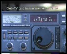
Screen capture of SM6CKUs digital test transmission via Astra 1A on February 9th, 2003