The mk2 Low-Cost Testcard Generator.
This article first appeared in CQ-TV magazine, issue 205
The original testcard generator article appeared in CQ-TV issue 201 and feedback from constructors all over the World has been very positive about it. It was based on work done nearly 20 years ago by Colin Edwards but compacted into a single chip along with a digital PAL encoder. By carefully redesigning parts of the logic it was possible to free some space that could be used for other features. The new design, imaginatively called mk2, is presented here. It is almost completely backward compatible with existing testcard EPROMS so very few existing testcards will require editing. In the new design it is not only possible to use block colour graphics as before, but also all user defined graphics and characters can be in colour too. As a bonus, the colour burst is now cleaner although it worked adequately before.
Hardware changes:
There are two changes to the hardware, one is the PLD itself but bear in mind the M4A5 can be erased and reprogrammed so you do not need to buy a new one. Just wipe it and put the new JEDEC codes in as replacements. The second change is just as easy; simply add one resistor, value 1K2 between the pin called TC_CLK (pin 14) and the junction of C5 and the seven chroma summing resistors (R8-R14). The resistor can be fitted on the copper side of the PCB. The TC_CLK function is no longer available but I dont think anyone ever used it anyway.
Testcard design changes:
As mentioned earlier, very few existing testcards will need any modification. Only those that used any of the first 16 characters in the font table will see a difference. The visible effect is that most of these characters will now appear as solid blocks. There has always been caution in the documentation of the CROPEDIT test card editor about using these characters as they are also used to shape the sync pulses. If any were used, their patterns can be copied to any of the remaining font positions and they can be used from there instead.
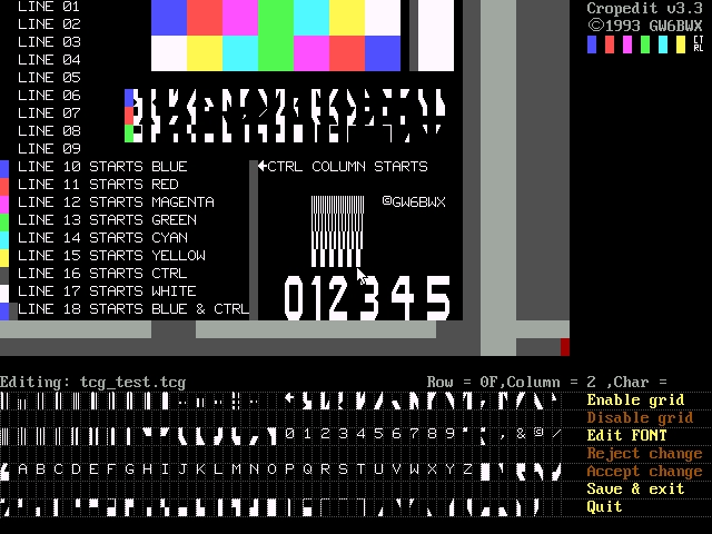
The major change is in the way the control character works. In all previous designs, including the original by Colin Edwards and those marketed by Cirkit, the Mendip Group and clones of these, the control character had to be inserted to change from graphics mode (with optional colour) to character mode (in white only). In the mk2 it does exactly the same but leaving it out allows the current colour to run into any following characters up to the end of each line. Its a little difficult to explain in words so take a look at the colour photographs, one is taken off-air (top) and the other is a screen snapshot of the Cropedit.com testcard editing program (bottom). The control character itself is still blanked (it appears grey in the editor) and colours picked from the menu still appear as solid blocks. Unfortunately, it is necessary to have at least one colour block to set the colour of any following characters, doing it any other way would lose backward compatibility. All lines start in white as before.

The PCB and schematic (except for the schematic change listed above) are both on the Test Card Generator page.
Click HERE to download the mk2 JEDEC file.
You may also be interested in G6UYJs adaptation of this design. He has used the PLD and schematic but built it with surface mount devices (SMD) making it even smaller. His web pages are at www.qsl.net/g6uyj